 Logic
SR latch (NOR)
An SR latch is the simplest memory circuit: two cross-coupled gates that store one bit.
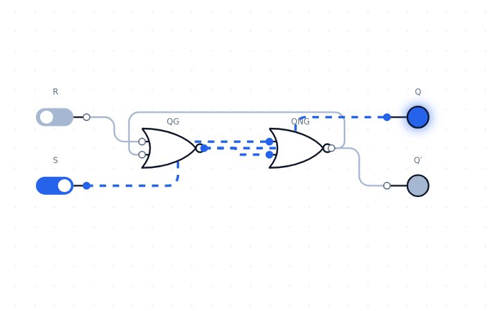
Open this circuit in LogicLab →
Boolean expressions
- Q⁺ = S + R′·Q
- S=R=1 is forbidden
How it works
In the NOR version a 1 on S sets Q to 1, a 1 on R resets Q to 0, and with both inputs 0 the latch keeps its previous value. Driving S and R high together is forbidden because both outputs go low and the final state becomes unpredictable.
Try it yourself
Two cross-coupled NOR gates remember one bit: S sets Q, R resets it, both low holds the value. Open the circuit, click the switches to change the inputs, and watch the LEDs and the waveform panel respond. You can edit the circuit, convert it to NAND-only or NOR-only gates, and save or export your version.
Related circuits
Reference: en.wikipedia.org/wiki/Flip-flop_(electronics)#SR_NOR_latch