 Logic
Gated D latch
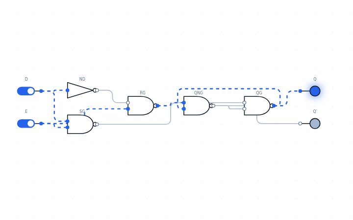
A gated D latch stores one bit: while its enable input is high the output follows the data input, and when enable goes low the last value is held.
Open this circuit in LogicLab →
Boolean expressions
- E=1: Q = D
- E=0: Q holds
How it works
An inverter makes S and R complementary so the forbidden state cannot happen. The enable gates both NAND inputs of an SR latch. Because the latch is transparent while enabled, a flip-flop (two latches back to back) is used when you need a value captured at a clock edge.
Try it yourself
While E is high Q follows D (transparent); when E goes low the last value is held. Open the circuit, click the switches to change the inputs, and watch the LEDs and the waveform panel respond. You can edit the circuit, convert it to NAND-only or NOR-only gates, and save or export your version.
Related circuits
Reference: en.wikipedia.org/wiki/Flip-flop_(electronics)#Gated_D_latch