 Logic
1:4 demultiplexer
A 1:4 demultiplexer takes one input bit and routes it to one of four outputs, chosen by two select bits.
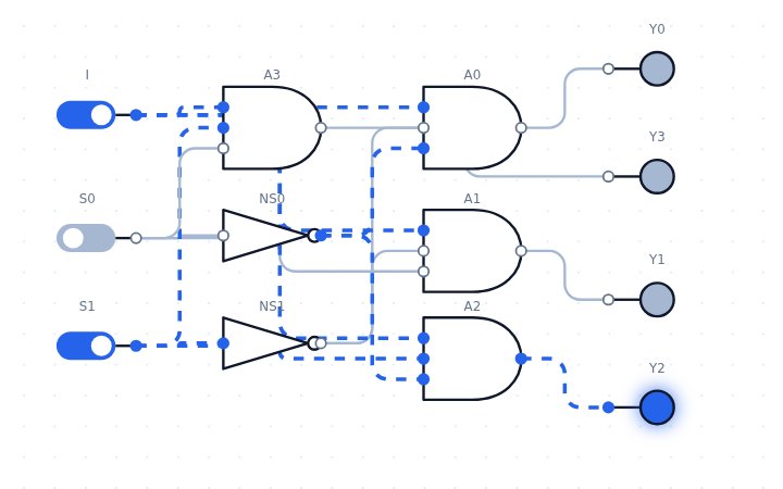
Open this circuit in LogicLab →
Boolean expressions
- Y0 = I·S1′S0′
- Y1 = I·S1′S0
- Y2 = I·S1S0′
- Y3 = I·S1S0
Truth table
| I | S0 | S1 | Y0 | Y1 | Y2 | Y3 |
|---|---|---|---|---|---|---|
| 0 | 0 | 0 | 0 | 0 | 0 | 0 |
| 0 | 0 | 1 | 0 | 0 | 0 | 0 |
| 0 | 1 | 0 | 0 | 0 | 0 | 0 |
| 0 | 1 | 1 | 0 | 0 | 0 | 0 |
| 1 | 0 | 0 | 1 | 0 | 0 | 0 |
| 1 | 0 | 1 | 0 | 0 | 1 | 0 |
| 1 | 1 | 0 | 0 | 1 | 0 | 0 |
| 1 | 1 | 1 | 0 | 0 | 0 | 1 |
How it works
It is the reverse of a multiplexer. Each output is an AND of the input with one combination of the select lines, so only the selected output follows the input while the other three stay 0.
Try it yourself
Routes one input to one of four outputs selected by S1 S0. Open the circuit, click the switches to change the inputs, and watch the LEDs and the waveform panel respond. You can edit the circuit, convert it to NAND-only or NOR-only gates, and save or export your version.
Related circuits
Reference: en.wikipedia.org/wiki/Multiplexer#Digital_multiplexers