 Logic
BCD to 7-segment decoder
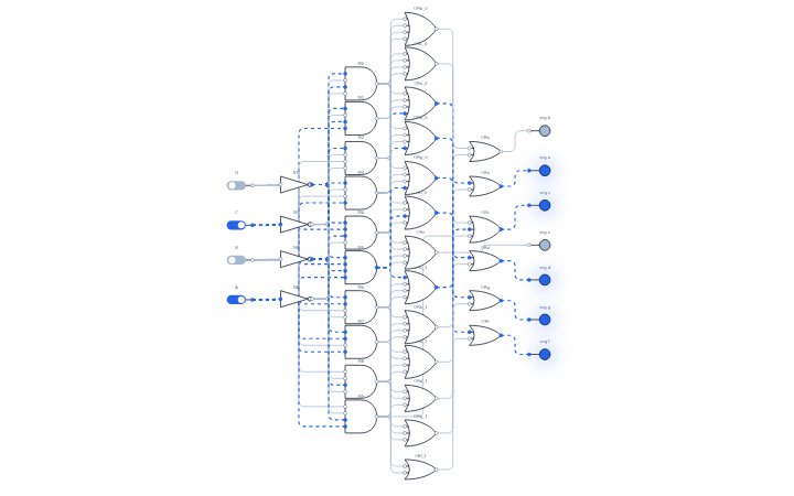
A BCD to 7-segment decoder turns a 4-bit binary-coded decimal digit into the seven signals that drive a 7-segment display.
Open this circuit in LogicLab →
Boolean expressions
- Segment x = OR of the digits that light it
Truth table
| D | C | B | A | seg a | seg b | seg c | seg d | seg e | seg f | seg g |
|---|---|---|---|---|---|---|---|---|---|---|
| 0 | 0 | 0 | 0 | 1 | 1 | 1 | 1 | 1 | 1 | 0 |
| 0 | 0 | 0 | 1 | 0 | 1 | 1 | 0 | 0 | 0 | 0 |
| 0 | 0 | 1 | 0 | 1 | 1 | 0 | 1 | 1 | 0 | 1 |
| 0 | 0 | 1 | 1 | 1 | 1 | 1 | 1 | 0 | 0 | 1 |
| 0 | 1 | 0 | 0 | 0 | 1 | 1 | 0 | 0 | 1 | 1 |
| 0 | 1 | 0 | 1 | 1 | 0 | 1 | 1 | 0 | 1 | 1 |
| 0 | 1 | 1 | 0 | 1 | 0 | 1 | 1 | 1 | 1 | 1 |
| 0 | 1 | 1 | 1 | 1 | 1 | 1 | 0 | 0 | 0 | 0 |
| 1 | 0 | 0 | 0 | 1 | 1 | 1 | 1 | 1 | 1 | 1 |
| 1 | 0 | 0 | 1 | 1 | 1 | 1 | 1 | 0 | 1 | 1 |
| 1 | 0 | 1 | 0 | 0 | 0 | 0 | 0 | 0 | 0 | 0 |
| 1 | 0 | 1 | 1 | 0 | 0 | 0 | 0 | 0 | 0 | 0 |
| 1 | 1 | 0 | 0 | 0 | 0 | 0 | 0 | 0 | 0 | 0 |
| 1 | 1 | 0 | 1 | 0 | 0 | 0 | 0 | 0 | 0 | 0 |
| 1 | 1 | 1 | 0 | 0 | 0 | 0 | 0 | 0 | 0 | 0 |
| 1 | 1 | 1 | 1 | 0 | 0 | 0 | 0 | 0 | 0 | 0 |
How it works
Ten AND gates detect digits 0 to 9. Each segment (a to g) is the OR of the digits that need it lit. Inputs 10 to 15 are not valid BCD, so no digit gate fires and the display stays blank.
Try it yourself
Decodes a 4-bit BCD digit (0 to 9) into the seven segment signals a to g; values 10 to 15 blank the display. Open the circuit, click the switches to change the inputs, and watch the LEDs and the waveform panel respond. You can edit the circuit, convert it to NAND-only or NOR-only gates, and save or export your version.
Related circuits
Reference: en.wikipedia.org/wiki/Seven-segment_display