 Logic
Basic logic gates
Logic gates are the building blocks of digital circuits: each one turns one or two input bits into one output bit.
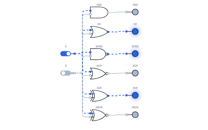
Open this circuit in LogicLab →
Boolean expressions
- AND = A·B
- OR = A+B
- NAND = (A·B)′
- NOR = (A+B)′
- XOR = A⊕B
- XNOR = (A⊕B)′
Truth table
| A | B | AND | OR | NAND | NOR | XOR | XNOR |
|---|---|---|---|---|---|---|---|
| 0 | 0 | 0 | 0 | 1 | 1 | 0 | 1 |
| 0 | 1 | 0 | 1 | 1 | 0 | 1 | 0 |
| 1 | 0 | 0 | 1 | 1 | 0 | 1 | 0 |
| 1 | 1 | 1 | 1 | 0 | 0 | 0 | 1 |
How it works
AND outputs 1 only when both inputs are 1. OR outputs 1 when at least one input is 1. NAND and NOR are AND and OR followed by an inverter. XOR outputs 1 when the inputs differ, and XNOR when they match.
Try it yourself
Two switches feed all six two-input gates so you can compare AND, OR, NAND, NOR, XOR and XNOR side by side. Open the circuit, click the switches to change the inputs, and watch the LEDs and the waveform panel respond. You can edit the circuit, convert it to NAND-only or NOR-only gates, and save or export your version.
Reference: en.wikipedia.org/wiki/Logic_gate